Plan the curves before the station
Avoid drawing track that cannot fit. A curve-first paper mock-up workflow using actual equipment requirements.
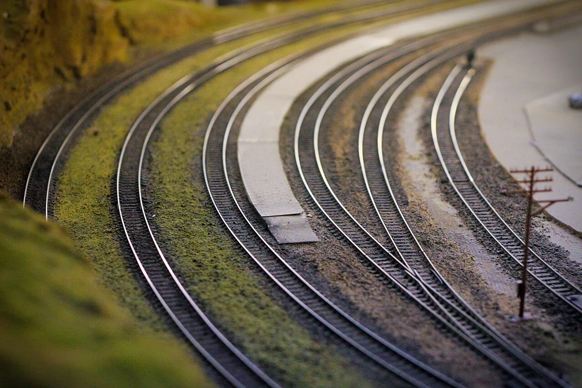
A station is easy to draw optimistically. A curve is less forgiving. Once the intended vehicles, track system and room are known, the turning portions of a plan often determine what space remains for everything else. Drawing those portions early helps prevent a beautiful straight scene from ending in a connection that only works on paper.
The NMRA's planning guide discusses minimum radius, transitions and the size of track components. Its track guide explains problems caused by abrupt reverse curves, while the rolling-stock guide connects equipment choices with the railway being modelled. Together they support a sequence in which vehicle needs inform geometry before scenic ambition fixes the footprint.
Begin with the intended equipment
Identify the vehicles that matter to the project, especially those expected to be most demanding in the proposed arrangement. Record exact model references and consult their current documentation. A broad label such as passenger coach or steam locomotive does not establish a minimum usable radius for every product within that category.
Separate a manufacturer's stated operating requirement from a visual preference. A vehicle may negotiate a curve while looking unlike the scene you want to depict. Conversely, a convincing broad curve is of little use if it leaves nowhere for the rest of the intended operation. Keep the mechanical and visual questions visible so one is not mistaken for the other.
Draw a real curve footprint
Work at a stated drawing scale and plot the track centreline accurately. Make a paper template representing the chosen curve, with an allowance for the relevant clearance and the surrounding scene. The centreline alone is not the outside edge of a train or the edge of the board.
The NMRA planning discussion includes layout squares as a way to account for turning space. You can use the underlying principle without adopting a whole planning system: reserve an honest footprint for the turn before fitting straight features between turns. Write the radius and the evidence behind it on the template rather than relying on its shape to preserve that information.
Treat the transition as occupied space
An easement gradually changes curvature between a straight and a circular curve. A sectional-track connection may instead change directly to its specified radius; not every arrangement includes an easement. Track geometry and connections still matter. If a gradual transition is planned, allocate its length explicitly. Do not draw a sweeping approach merely as an attractive line if the selected track components cannot produce it.
Where sectional track is involved, use the actual pieces or accurate manufacturer templates. With flexible track, a freehand line is still only a proposal until its shape can be laid consistently. The point is not to favour one system. It is to make sure the plan describes the material that will be built, rather than a line that changes character during construction.
Look closely at reverse curves
The NMRA track guide explains how adjacent curves in opposite directions can place coupled vehicles in conflicting positions. This is particularly relevant where a crossover or compact throat creates a reverse movement that is easy to overlook in a larger drawing.
Trace the intended train through each direction change, including the couplings between vehicles. Do not assume a radius that works for one isolated curve proves the entire sequence. Consult the relevant product and track information, and plan a physical trial before permanently fixing complex geometry. The trial should represent the actual vehicles and connections you intend to use.
Test the station against the curve
Only after the turning space is reserved should the station footprint be fitted. Add the longest intended train, platform, buildings and any access that the scene requires. If the station reaches into the curve, identify the consequences rather than quietly shortening the platform in the drawing.
In a hypothetical small room, the first revision might reduce the number of platform tracks. A second might shorten the chosen service, and a third might change the layout's shape. None is automatically correct. Compare which change sacrifices the least important part of the brief while preserving the practical geometry that the trains require.
Keep a geometry decision record
For each critical curve, retain the chosen radius, track reference, vehicle assumptions, clearance question and trial outcome. Record whether the dimensions are measured, taken from current documentation or still provisional. If you later buy longer equipment, the record shows which parts of the design need reassessment.
A curve-first plan is not an instruction to fill the room with circles. It is a way to expose the hardest spatial commitments before buildings and track counts make them emotionally difficult to change. The final drawing should leave no unexplained leap between the chosen vehicles and the route they are expected to follow. Where evidence remains missing, preserve the question and postpone permanent work on that section.
Label templates with their drawing scale too. A reduced photocopy or resized print can preserve a convincing shape while invalidating every dimension that made the original planning exercise useful.
Take it to the workbench
A field sheet for this article. Use your browser’s print command or copy the headings into your project notebook. Keep facts, observations and open questions distinct.
| Exact vehicle references | Your notes |
|---|---|
| Documented curve requirements | Your notes |
| Track template and drawing scale | Your notes |
| Transition space | Your notes |
| Physical trial still needed | Your notes |
A failed paper fit
Hypothetical worked example. A curve template fits the room, but its vehicle-clearance outline overlaps the station building. Moving only the centreline on the drawing does not solve the conflict. Reduce the station footprint or reconsider the geometry, then check the exact equipment requirements again.
This is an editorial exercise, not a report of a physical test.
Sources & further reading
- National Model Railroad Association — Layout Planning
- National Model Railroad Association — Laying Track
- National Model Railroad Association — Motive Power & Rolling Stock
Sources support the factual background. Worksheets and hypothetical exercises are editorial proposals, not reports of tests performed by this publication. Consult the relevant current product documentation before applying product-specific advice.