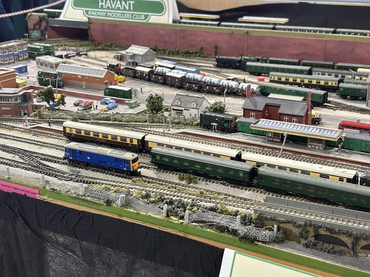
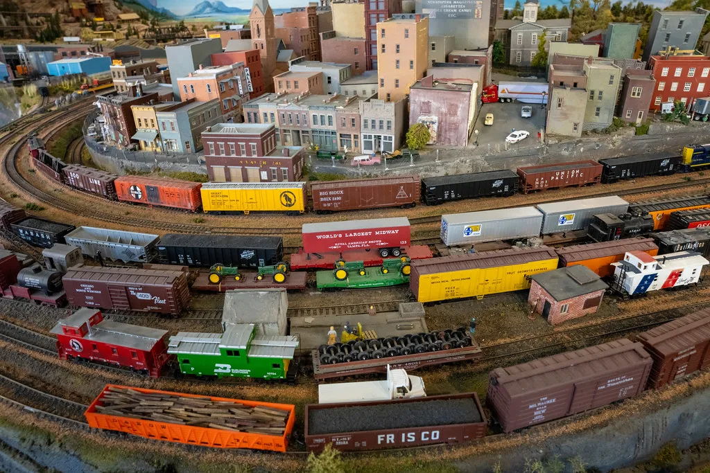
A station needs more than a platform
Allocate station space with buildings and circulation. A footprint overlay combining train, platform and street needs.
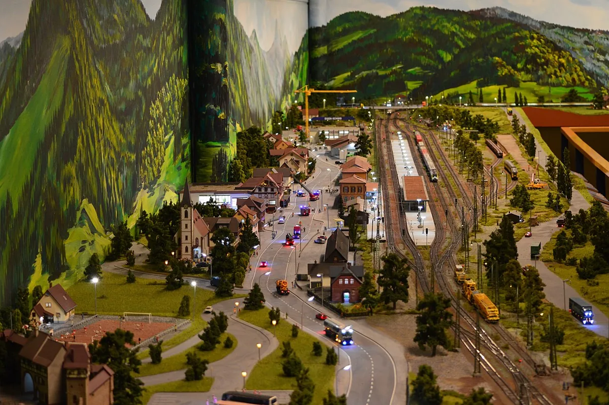
A model station is often planned as a length of platform squeezed beside an already fixed track. The building then occupies the remaining gap, and the road arrives wherever space permits. Reversing that sequence produces a more convincing place. Treat the station as a group of connected activities, each with a footprint and a reason to meet the others.
The NMRA's structures guide relates building choices to time, place and available space. Its planning guide asks builders to account for structures alongside track geometry, while the operations guide connects locations with the work trains perform there. The overlay method below combines those relationships without pretending to reproduce a particular historic station.
Name the station's job
Begin with a sentence describing the place. A small through station, a passenger terminus and a combined passenger-and-goods location imply different movements. Add the service you intend to show and the parts of the station visible to the viewer. A scenic fragment can be persuasive without depicting the entire real-world facility.
For a fictional example, assume a modest passenger stop with one visible platform, a station building and a road approach. State that assumption explicitly. It allows a focused exercise while preventing the drawing from being mistaken for a universal station plan. If goods handling or locomotive servicing is later added, those are new requirements with their own space consequences.
Lay down the train layer
Draw the intended train and the relevant track at the chosen planning scale. Use measured model lengths where available, including couplings. Mark the stopping position and the movement into and out of the scene. Keep curved-track requirements and vehicle clearances separate from the apparent width of the track line.
Do not extend a platform merely until it looks balanced on the page. Compare its proposed use with the intended service and research any prototype-specific arrangement. If the model deliberately compresses the scene, record what is being omitted or shortened. Selective compression can be a design choice, but it should not quietly become a claim of historical accuracy.
Add the building layer
On a second sheet or tracing overlay, mark the real footprint of the chosen model building. Include projecting roofs, steps and other features that matter to its placement. A rectangular kit base may not describe every part that needs room. Paper mock-ups help expose those differences before assembly fixes a building's position.
Identify the public entrance, platform-side openings and any service side visible in the scene. These observations guide the building's orientation. A handsome front facing the viewer can still leave the implied passenger route blocked. Research photographs or plans should support a specific historic arrangement; for a fictional place, make the circulation legible rather than claiming undocumented authenticity.
Trace the human route
Use a third overlay for movement between the road approach, entrance and platform. Add vehicle access only where it serves the chosen scene. The drawing need not become a transport-engineering plan; it should simply explain how people and supplies reach the building rather than appearing there through scenery.
Look for contradictions: an entrance opening directly into a hedge, a path blocked by a signal-box footprint, or a yard with no apparent road connection. Resolve the important relationships first. Small details such as benches and signs belong after the main routes make sense, because attractive accessories cannot repair an impossible entrance.
Reserve maintenance access
A roof, canopy or platform can obstruct the operator's view of a vehicle. Mark where uncoupling, inspection or rerailing may be needed and compare those places with the scenic layers. If a building must lift away, show its removal direction and a temporary resting place.
Keep this operational access distinct from the fictional passenger route. One belongs to the real modeller; the other belongs to the miniature scene. They can coexist through thoughtful placement, but a convincing road does not prove that the hidden track behind the station can be maintained. Test both relationships before committing scenery or fixing structures permanently.
Choose what the viewer needs to see
Combine the overlays and view them from the intended front edge. Decide which elements explain the station and which can continue beyond the scenic boundary. A road disappearing behind a building may suggest a wider town without requiring every street to be modelled. An omitted feature should leave a coherent impression rather than an unexplained dead end.
Keep a short station record with intended service, train length, model-building dimensions, circulation choices, access provisions and evidence still required. The finished scene earns its space through these relationships. It becomes recognisable as a place where railway activity happens, rather than a collection of attractive objects fitted around the rails after the important decisions have already been made.
Photograph the combined paper overlays before moving them. That record preserves the reasoning behind a building's position when later work removes the temporary lines and the arrangement starts to look inevitable.
Take it to the workbench
A field sheet for this article. Use your browser’s print command or copy the headings into your project notebook. Keep facts, observations and open questions distinct.
| Intended passenger service | Your notes |
|---|---|
| Measured train footprint | Your notes |
| Building projections | Your notes |
| Public and service routes | Your notes |
| Model maintenance access | Your notes |
Three overlays disagree
Hypothetical worked example. The train layer fits, but the canopy on the building layer covers the uncoupling location. The street layer also puts a hedge across the entrance. Move the building mock-up and repeat both access checks; a longer platform alone fixes neither conflict.
This is an editorial exercise, not a report of a physical test.
Sources & further reading
- National Model Railroad Association — Structures
- National Model Railroad Association — Layout Planning
- National Model Railroad Association — Operations
Sources support the factual background. Worksheets and hypothetical exercises are editorial proposals, not reports of tests performed by this publication. Consult the relevant current product documentation before applying product-specific advice.