Give a building the ground it needs
Integrate a structure instead of placing it on top. A building-edge checklist for foundations, yards and paths.
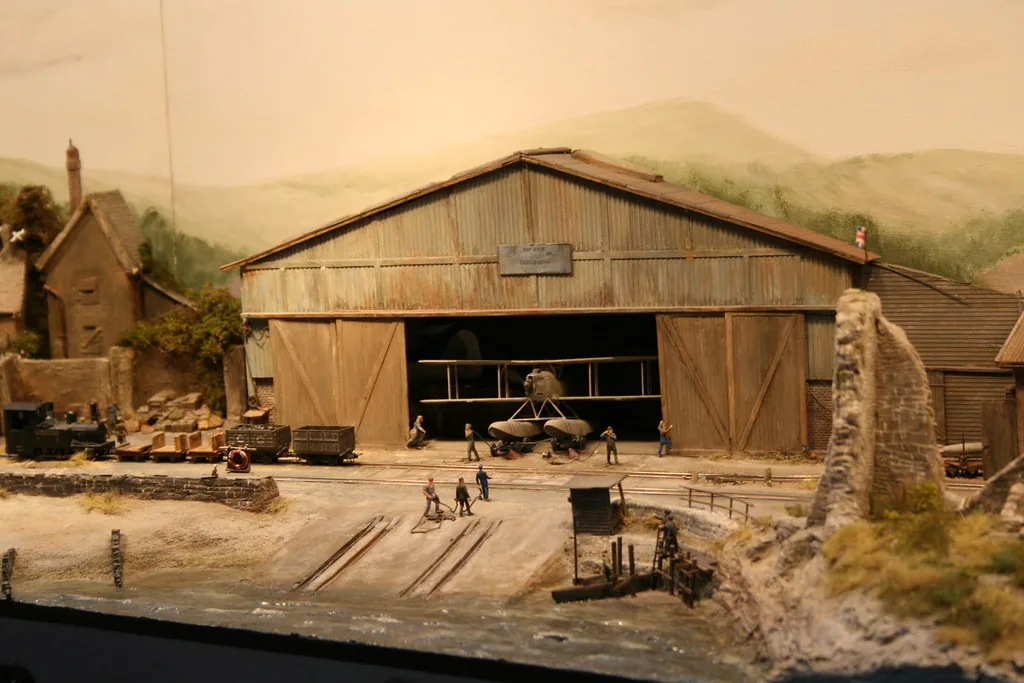
A detailed building can look temporary when its base appears to float above the scenery. The effect is not always a problem with the kit. It may be a missing relationship between the structure, ground, access routes and neighbouring activity. Planning that edge before final installation often contributes more than adding another set of small architectural details.
The NMRA structures guide explicitly discusses integrating structures with surrounding scenery. Its scenery and weathering guides add context for ground and surface treatment. The building-edge checklist below is a visual and practical planning method, not structural foundation advice or a universal prescription for adhesives and finishes.
Inspect the complete footprint
Record the actual model dimensions, including projecting steps, roofs and attached platforms. Compare them with the space reserved during planning. A nominal rectangular base can hide the parts most likely to conflict with a road or neighbouring track.
Identify each visible entrance and the side it serves. Mark which elevations will be viewed and which are needed for access. If the model represents a particular building, preserve the reference evidence for orientation and surrounding features. Do not assume the most decorative facade belongs at the front of the layout if that position contradicts the intended scene.
Decide how it meets the ground
Examine the lower edge and determine which parts should appear embedded, raised or connected with another surface. Use suitable references for a specific place or building type. For a fictional composition, choose an understandable relationship without claiming a documented historic construction detail.
Create a temporary ground profile around a simple mock-up. Look for an even unexplained gap or a sudden mound that exists only to conceal the model base. The goal is not merely hiding a join. It is making the visible relationship between building and land seem intentional at the scene's normal viewing distance.
Connect entrances and working areas
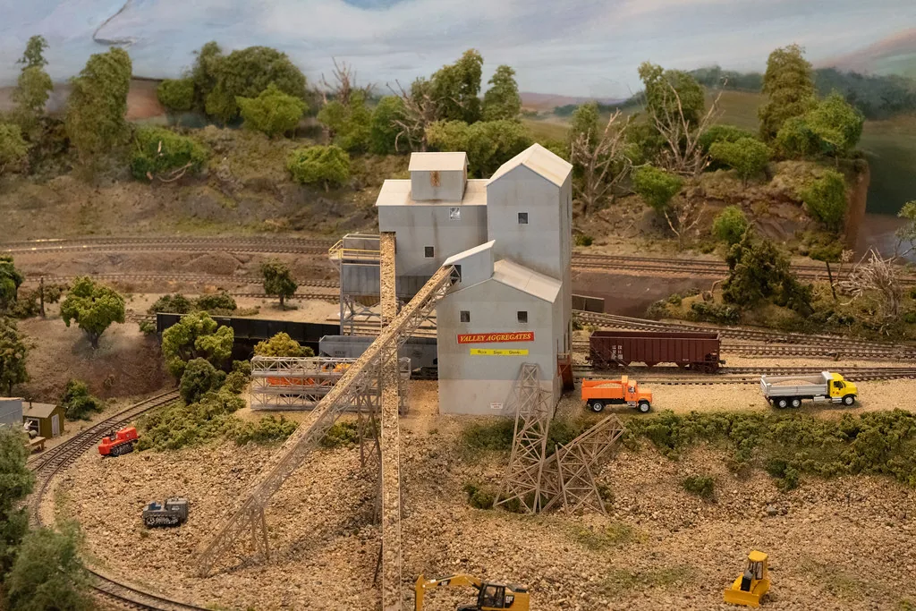
Trace a route to the doors, loading openings and platforms that matter to the scene. A convincing structure needs enough surrounding space to explain its use. A warehouse loading door facing an inaccessible patch of scenery weakens the story even if every brick is beautifully painted.
Do not fill these routes with decorative clutter before their purpose is clear. Place a few temporary objects and compare the resulting view. If a vehicle or figure establishes the relationship effectively, additional accessories may be unnecessary. Retain only details that support a coherent activity or an evidence-backed feature of the represented place.
Plan removability early
Determine whether the structure must be removed for track access, transport or attention to interior equipment. Mark the lifting direction and suitable handling points according to the actual model. A delicate roof detail is not automatically a safe place to lift a building.
If removal is needed, design the scenic boundary so it does not depend on tearing away ground cover. Keep a clear resting place during maintenance and record any loose parts that must be removed first. The practical join may remain visible under close inspection; a small honest compromise is preferable to a permanently inaccessible mechanism hidden beneath a flawless edge.
Coordinate colour and surface condition
Compare the building with nearby ground and other structures under the intended lighting. The NMRA weathering discussion distinguishes general appearance from reproducing a specific photographed condition. Decide which approach applies to the scene before treating every surface alike.
A newly maintained building can belong beside older surroundings if the interpretation supports that relationship. Uniform dirt is not required for coherence. Use references or clearly stated fictional choices, and keep any product-specific preparation and application method tied to current instructions. A visual integration plan does not establish chemical compatibility between a coating and the model material.
Test the edge in context
Place the structure or a representative mock-up with the relevant track, vehicles and surrounding scenery. View it from the intended positions. Check whether ground texture overwhelms small details or whether a bright base strip draws attention away from the main subject.
Photograph alternatives with comparable framing so later decisions do not rely only on memory. Keep operational checks separate: visual fit does not demonstrate train clearance or access for uncoupling. Where the building stands near working track, assess the actual equipment and geometry before fixing the position or completing the ground around it.
Keep an installation note
Record the selected position, orientation, ground relationship, material sample references and removal procedure. Add photographs before hidden areas become difficult to inspect. Identify any unresolved historic or product question instead of letting an attractive finished arrangement imply it has been answered.
Revisit the note when roads, platforms or nearby track change. Integration is a relationship, so changing one neighbour can alter the building's apparent purpose and practical access. A well-set structure feels as though its surroundings belong to it. That effect comes from connected decisions at its edges, not simply from the complexity of the model placed in the centre.
Take it to the workbench
A field sheet for this article. Use your browser’s print command or copy the headings into your project notebook. Keep facts, observations and open questions distinct.
| Complete building footprint | Your notes |
|---|---|
| Ground-edge relationship | Your notes |
| Entrance and working route | Your notes |
| Removal procedure | Your notes |
| Colour and condition interpretation | Your notes |
An edge that must lift
Hypothetical worked example. The depot must be removed for access. A proposed continuous ground strip would glue its base to the scene. Reserve a removable boundary in the mock-up and record where the building rests, rather than treating a seamless join as the only successful finish.
This is an editorial exercise, not a report of a physical test.
Sources & further reading
- National Model Railroad Association — Structures
- National Model Railroad Association — Scenery
- National Model Railroad Association — Weathering
Sources support the factual background. Worksheets and hypothetical exercises are editorial proposals, not reports of tests performed by this publication. Consult the relevant current product documentation before applying product-specific advice.