A module joins more than two pieces of wood
Define a club interface before building a module. An interface agreement covering mechanical, track and control boundaries.
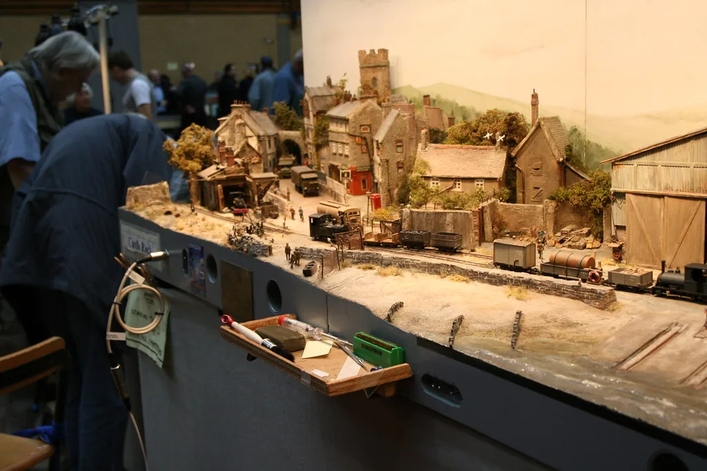
A modular railway is a collaboration at its edges. The landscape between those edges may express an individual modeller's interests, but the ends must work with someone else's construction. Matching board width alone is not enough. Track position, support, connections and the way trains are controlled all belong to the interface conversation before the first section is built.
The NMRA's module introduction explains the role of shared specifications in joining portable sections. FREMO's N-RE frame guidance provides a concrete example of a particular system defining profiles and construction provisions. Use these sources to understand the principle of agreement; obtain the actual requirements of the group you intend to join before adopting any dimensions.
Name the system and its owner
Write the group's chosen module system, the relevant edition of its requirements and the person or role responsible for clarification. A note saying “built to club standard” becomes ambiguous if the group has more than one practice or later changes a detail.
Ask whether the planned section is an interchangeable module or one part of a larger set that must stay together. The NMRA discussion permits a module to comprise several tables with controlled outer interfaces. That distinction can allow freedom within a grouped scene while keeping the boundary understandable. Record which joints are internal and which must connect with other members' work.
Separate the interface layers
Divide the agreement into mechanical, track, control and presentation layers. Mechanical requirements concern the physical join and support arrangement. Track requirements concern position, geometry and the relevant wheel-and-rail system. Control requirements concern the documented electrical and operational connections. Presentation requirements concern the agreed scenic transition and visible finish.
For each layer, identify the authoritative document or group decision. Do not use a scenic preference as evidence for a technical connection, or assume a familiar connector establishes an entire control-system match. Electrical arrangements require the relevant current documentation and competent implementation. This article supplies a planning record, not a wiring prescription.
Draw a boundary sheet
Prepare one labelled drawing for each end of the module. Show the orientation, track direction and reference features used by the chosen system. Include the exact source of dimensions rather than copying a diagram without its title or notes. If the ends differ, do not rely on memory to identify them.
FREMO's N-RE frame page describes several profiles and details specific to that context. It illustrates why a profile name matters, but it does not make one profile appropriate for every club. A boundary sheet should describe the system being built, including any approved variation, rather than combine attractive details from unrelated standards.
Reserve the working space
A connection needs room to be assembled and inspected. Consider the space behind an end plate, beneath the track and around any fastening or connector. The N-RE guidance explicitly addresses space for connections and mechanisms during construction, showing that access belongs in the design rather than in last-minute improvisation.
Mark where hands and tools approach when neighbouring modules are present. Check the setup sequence against scenery and support positions. A connection accessible on an empty workbench may be obstructed once two finished sections stand together. Keep a temporary clearance zone in the construction drawing until the interface procedure has been assessed in its intended arrangement.
Agree on the scenic handshake
At the visible boundary, discuss terrain height, broad colour relationships and features that continue across the join. The aim is not identical craftsmanship or a prohibition on individuality. It is avoiding an unexplained road ending at a cliff or a stream meeting an incompatible landform.
Use a simple photograph or mock-up of the intended edge and label what is fixed versus optional. Record whether loose scenic pieces bridge the joint and who supplies them. Keep those pieces out of technical connection areas. A neat scenic transition should never conceal a connection that needs inspection or make disassembly depend on damaging finished work.
Verify the agreement together
Before finishing the surrounding scenery, arrange a suitable trial connection with the group or a representative interface. Record what was checked, which documents were used and what remained unresolved. A successful fit to one neighbour is valuable evidence, but do not describe it as verification against every possible module.
Retain the boundary sheets, photographs, agreed exceptions and assembly sequence with the module. Update them when a connection changes. A good interface agreement makes collaboration less dependent on the original builder being present. It lets the scenic centre remain personal while giving the shared railway a dependable, documented way to come together.
Keep unresolved decisions in a separate list with an owner and a practical next step. For example, the group might need to confirm which end profile applies before a frame is cut. Naming that dependency is more useful than a general note to check compatibility later, when several members may already have built incompatible parts.
Take it to the workbench
A field sheet for this article. Use your browser’s print command or copy the headings into your project notebook. Keep facts, observations and open questions distinct.
| Chosen system and edition | Your notes |
|---|---|
| Boundary orientation | Your notes |
| Mechanical and track interface | Your notes |
| Control-document reference | Your notes |
| Scenic join and trial evidence | Your notes |
One internal join
Hypothetical worked example. Boards A and B always travel as a pair, while their outer ends join other members' modules. Mark A/B as an internal join and identify the published requirements for the two outer ends. A scenic preference inside the pair cannot override those outer interfaces.
This is an editorial exercise, not a report of a physical test.
Sources & further reading
- National Model Railroad Association — Introduction to Layout Modules
- FREMO — Frame of a Module
- National Model Railroad Association — Standards and Recommended Practices
Sources support the factual background. Worksheets and hypothetical exercises are editorial proposals, not reports of tests performed by this publication. Consult the relevant current product documentation before applying product-specific advice.