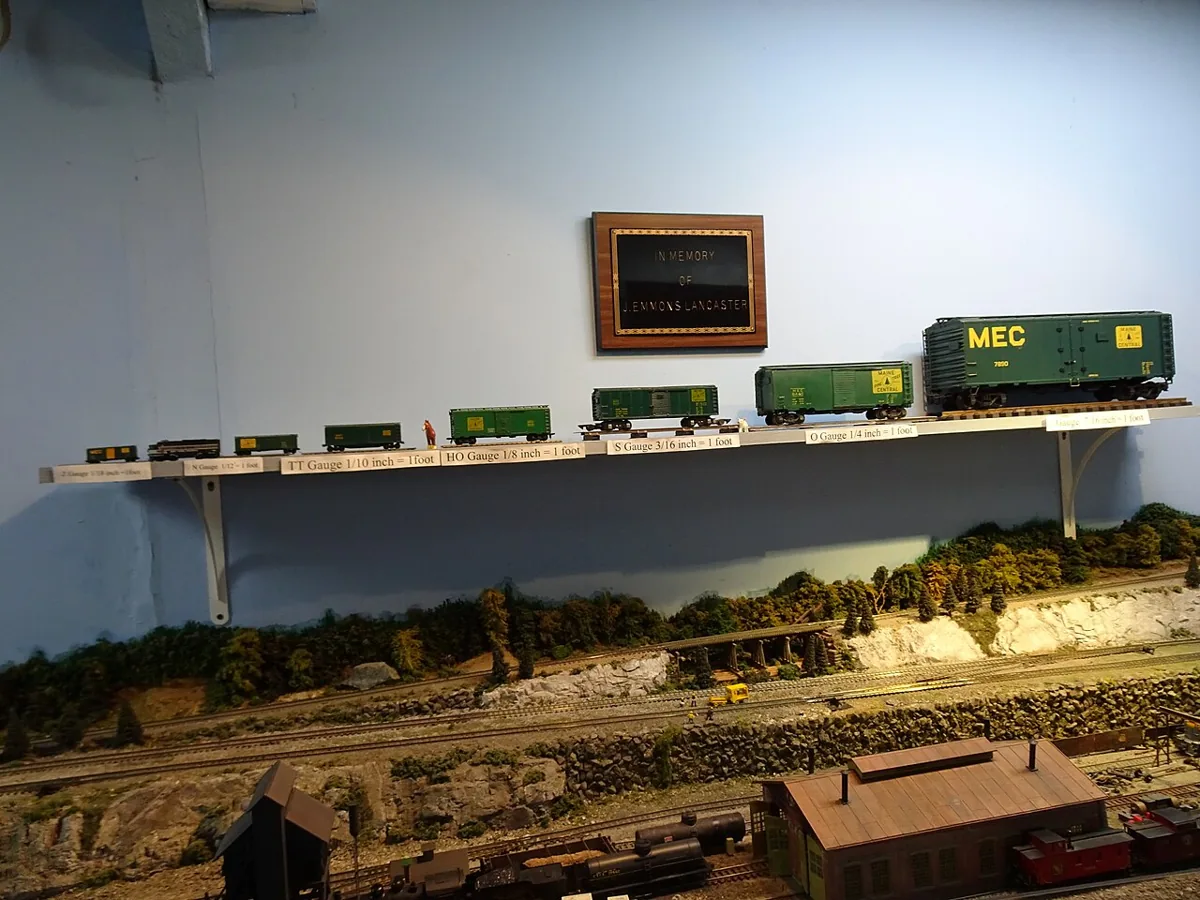
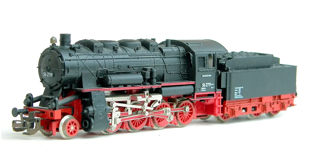
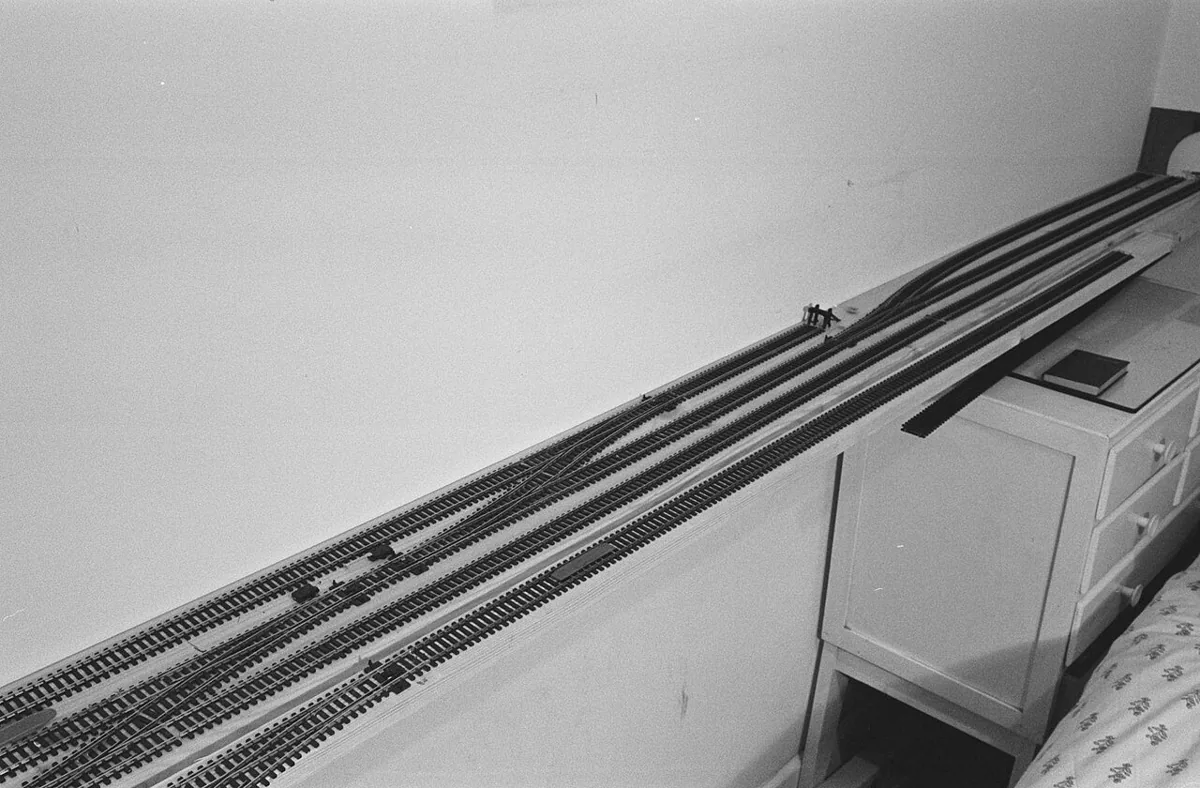
From full size to model size without guessing
Convert prototype dimensions consistently. Worked arithmetic and a dimension ledger with units and assumptions.
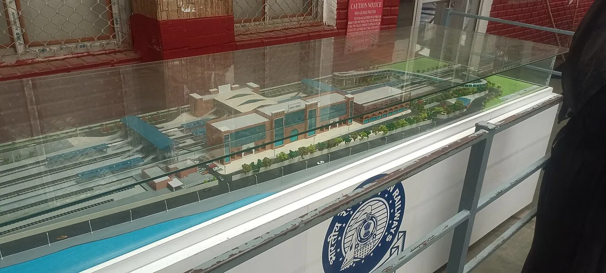
A model dimension is only as reliable as the measurement and units that produced it. A calculator can divide perfectly while starting from the wrong drawing scale or mixing feet with millimetres. Before cutting a wall or placing a platform, keep the conversion visible enough that another person could reproduce it from the same evidence.
The NMRA's tools guide distinguishes ordinary measuring tools from model scale rulers. Its structures guide discusses drawings and reference measurements, while its standards index provides the context for named modelling conventions. The worked examples here use fictional dimensions to demonstrate arithmetic rather than assert measurements for a real railway building.
Put both dimensions in one unit
For a ratio written one to one hundred, divide the full-size dimension by one hundred to obtain the model dimension in the same unit. A fictional wall twelve metres long becomes zero point one two metres. Expressed in millimetres, that is twelve thousand divided by one hundred, giving one hundred and twenty millimetres.
Write the unit at every step. A bare number such as twelve can refer to metres, feet or a measurement taken from a print. The calculation is not complete until its starting meaning and final unit are explicit. Choose a working unit appropriate to the task and convert the input before applying the reduction ratio.
Separate real dimensions from drawing dimensions
A dimension printed on a drawing normally describes the represented object, subject to the drawing's own conventions. A distance measured with a ruler across a reproduced page is different evidence. Printing, scanning or resizing can alter that physical page measurement without changing any dimension labels.
Suppose a fictional plan depicts a ten-metre wall at one to fifty. On an accurately reproduced drawing the wall would measure two hundred millimetres. To model it at one to one hundred, the model length is one hundred millimetres. You can calculate directly from the ten-metre prototype dimension, avoiding an unnecessary dependence on the reproduction's physical size.
Convert between drawing scales deliberately
If only a trustworthy drawing measurement is available, relate its scale to the intended model scale. A drawing at one to fifty reduced for a model at one to one hundred needs half the measured drawing dimension. Record both ratios and the resulting multiplier so a future copy does not lose the reasoning.
MOROP's NEM 010 English edition includes a scale-conversion example using this relationship. That principle does not establish that an arbitrary downloaded image retains its original scale. Check a known dimension on the reproduction, and keep any uncertainty visible. Do not describe a resized screenshot as a scale drawing merely because its source once was one.
Record evidence in a dimension ledger
Use one line for each important dimension. Include the feature name, full-size value if known, source, source unit, chosen ratio, calculated model value and intended marking precision. Add a field for measured, documented or estimated. Those labels describe evidence quality, not the quality of the finished model.
For a building, record length, width, openings and roof features separately. If one wall is documented but another inferred from a photograph, do not give them identical confidence. The ledger lets you improve weak evidence later without disturbing calculations based on reliable dimensions. It also explains why two equally neat numbers may deserve different treatment at the workbench.
Mark and measure realistically
The NMRA tools discussion identifies measurement and marking tools. In applying a calculated dimension, distinguish the width of your own marking line from the intended measurement. A result displayed to several decimal places does not guarantee that the line, tool or material can reproduce it. Distinguish the mathematical result from the practical dimension you intend to mark.
Decide where rounding is appropriate and record it once. Repeatedly rounding intermediate values can accumulate error across a row of openings. Work from a stable reference edge and preserve the unrounded calculation in the record. Material thickness and assembly method can also affect cut dimensions; they are additional construction decisions, not reasons to alter the prototype arithmetic silently.
Check the answer a second way
Reverse the conversion as a quick reasonableness check. A one hundred and twenty millimetre model wall at one to one hundred corresponds to twelve thousand millimetres, or twelve metres, full size. If that does not match the intended starting dimension, inspect the units and ratio before blaming the calculator.
Finally compare related dimensions visually and numerically. A door taller than the entire wall may reveal a transcription error even when each individual division was correct. Keep the ledger beside the drawing and identify it in the project notes. The benefit is not numerical decoration; it is a traceable route from source evidence to a dimension that can be used, checked and revised without guessing.
Label every printed working drawing with the intended scale and a known reference length. Check that reference on the actual print before using it to transfer dimensions to material.
Take it to the workbench
A field sheet for this article. Use your browser’s print command or copy the headings into your project notebook. Keep facts, observations and open questions distinct.
| Feature and source | Your notes |
|---|---|
| Original value and unit | Your notes |
| Reduction ratio | Your notes |
| Unrounded model result | Your notes |
| Practical marking dimension | Your notes |
A traceable calculation
Hypothetical worked example. The fictional wall is 12m, or 12,000mm. At 1:100 its model length is 120mm. A 120mm paper measurement is usable only if the print has retained its intended size; the labelled prototype dimension remains the stronger starting evidence.
This is an editorial exercise, not a report of a physical test.
Sources & further reading
- National Model Railroad Association — Standards and Recommended Practices
- National Model Railroad Association — Tools
- National Model Railroad Association — Structures
- MOROP — NEM 010: Scales, Nominal Sizes, Gauges — English edition 2011
Sources support the factual background. Worksheets and hypothetical exercises are editorial proposals, not reports of tests performed by this publication. Consult the relevant current product documentation before applying product-specific advice.